|
SCART is a 21-way connector used to connect video equipment together. Almost impossible to plug into the back of a TV set or other AV equipment if you can't see the socket and is prone to coming loose and causing all sorts of amusing faults. It provides connections for video input and output, audio input and output, RGB video and control signals (2 comms. data connections, blanking, function switching). SCART stands for 'Syndicat des Constructeurs d'Appareils Radiorécepteurs et Téléviseurs'. Can also go under the names of Peritel connector, and Euro-connector (many of us could come up with other names for it no doubt). It was imposed originally on the French market, all TV equipment sold there had to scart connection. Then by European Community directive on the rest of us fortunate EU citizens, TV and VCR equipment sold in the EC which have external video line connections have to be supplied with SCART connectors - lucky us, another "improvement" in our lives! Like a lot of other seemingly good ideas these should make our lives easier but in practice, like most over regulated bureaucratic things, it can be the opposite. If you buy a TV, DVD player, VCR etc and it is the same make, and use the SCART leads they supplied with the pieces of equipment, it will all work as intended - well there is a good chance anyway. If however you mix and match stuff of different ages and manufacturers and use a standard SCART cable from Maplins, Dixons or any other store, then weird things can happen..... Best to do a search in Google for the most up-to-date info on all the equipment and try to figure out the pin-outs if problems arise. Below are the details of how these connector used to be arranged, though they may well have been altered since this information was gathered. So again if in doubt Google is your friend.
|
|||||||||||||||||||||||||||||||||||||||||||||
|
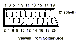
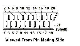
Diagram shows numbering of pins in connector, viewed from solder side of plug in the first image and from the pin mating side in the second. Note that there are 20 pins, the 21st connection is the metal shell of the connector, to which the screening braid of the cable should be connected, although on most of the leads I have bought no one seems to bother. Note 1: Pin 8 provides function switching. Applying 9.5-12V to the pin will cause a compatible TV or VCR to switch to the AV (SCART) input. It may also switch on the equipment from standby. Applying 0V or leaving unconnected will switch back to TV. Some TV's also use this pin to select the aspect ratio. Applying 5-8V to pin 8 will switch to 16:9 mode. This may be used by DVD players to set TV to correct ratio. Connect ground to pin 14 or pin 18. |
|
||||||||||||||||||||||||||||||||||||||||||||
|
|||||||||||||||||||||||||||||||||||||||||||||

