|
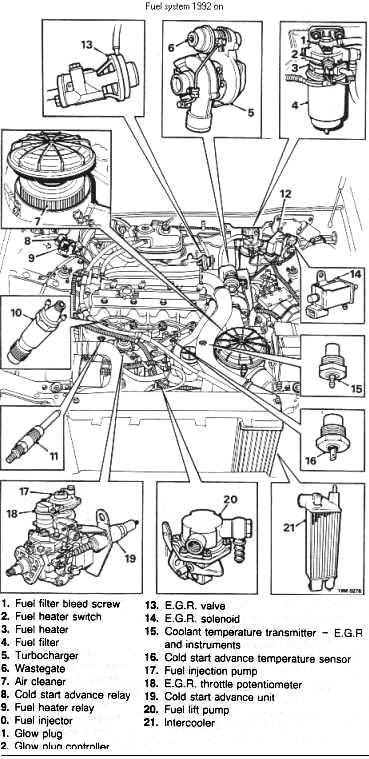
Fuel is drawn from the tank by
a mechanical lift pump and passes to the injection pump via a filter
incorporating a heating element. In addition to removing particle contamination
from the fuel, the filter incorporates a water separator, which removes and
stores both bound and unbound water.
The injection pump meters a
precisely timed, exact quantity of fuel to the injectors in response to throttle
variations, injection timing varying with engine speed. Any excess fuel
delivered to the injection pump is not injected, passing back to the tank via
the fuel return line.
Fuel is injected in a finely
atomised form into a pre - combustion chamber in the cylinder head where it
ignites. The burning fuel expands rapidly into the main combustion chamber,
creating extreme turbulence which mixes the burning fuel thoroughly with the
compressed air, providing complete combustion.
Cold Starting is assisted by
glow plugs, a cold start advance unit and a high idle setting.
Glow plugs
Glow plug operation is
controlled by a timer unit, start relay and resistor. When the ignition is
turned on the timer unit is energised. The glow plugs start to operate and a
warning light on the dashboard illuminates, remaining illuminated until the glow
plugs are automatically switched off.
The length of time the glow
plugs will operate is dependent on under bonnet temperature, which is monitored
by a sensor located in the timer unit. Starting the engine results in the power
supply to the glow plugs passing through the resistor, which reduces their
operating temperature. The glow plugs are cut out either by the temperature
sensor in the timer, or by a microswitch on the injection pump which operates
when the throttle is depressed.
Cold start advance - up to 1992 models
The cold start advance unit is
connected to the engine cooling system via hoses. It contains a temperature
sensitive element which is retracted when cold and pulls the advance lever, via
cable, towards the rear of the pump against spring pressure. As coolant
temperature rises, the cold start element expands releasing tension on the cable
and allowing spring pressure to move the advance lever forwards.
Cold start advance - 1992 models on
The cold start advance unit
contains a temperature sensitive element which is retracted when cold. pulling
the advance lever, via cable, towards the rear of the pump against spring
pressure, thus advancing injection timing. When the engine has started and the
temperature has risen to 30°C, the temperature sensor in No. 3 cylinder head
will close supplying an earth for the cold start advance relay. The energised
relay switches a supply to the cold start advance unit. The element heats up,
releases tension on the cable and allows spring pressure to move the advance
lever forwards, thus retarding injection timing.
High idle
High idle is obtained by the
ball pin on top of the advance lever holding the engine speed lever away from
its stop when the cold start advance unit is in the retracted position.
Exhaust Gas Recirculation (E.G.R.)
Operation of the E.G.R system
is dependant on the following:
- Engine temperature - must be
above 40°C:
- Engine speed - must be
between 2000 4200 rev/min;
- Engine load - calculated by
engine speed and throttle position.
The E.G.R. control unit
monitors signals from the tachometer (engine speed), throttle potentiometer
(throttle position) and coolant temperature transmitter (engine temperature)
and, when all conditions are met, the control unit switches an earth path to the
E.G.R. solenoid.
Once energised, the E.G.R.
solenoid directs manifold vacuum to the E.G.R. valve. The E.G.R. valve opens and
directs a quantity of exhaust gas back into the inlet manifold and from there
into the engine.

|