Rover 825SD 800 Coupe 825i SD1 and Land Rover Web Site
![]()
A non-technical explanation (as much as possible!) and some testing / fault finding
The diagram below is a general representation, not a specific alternator.
|
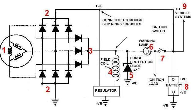
1.
The stator windings, this is a 3 phase machine, it has 3 sets of coils.
Description The alternator is a self exciting type, or in other words it supplies its own field or exciting current once it is running. But it still needs a source of field current before it can start the generating process. This is where the ignition warning lamp comes in, yes the dashboard light is part of the charging circuit. Should the bulb blow there would be theoretically no charge available (although there is usually enough residual magnetism in the field coil to allow it to work). To prevent any chance of it not working because of this, a resistor is fitted in parallel with the light bulb. When the ignition is turned on current passes through the bulb, field winding on the rotor and the regulator to earth (-VE). This small current in the field produces a weak magnetic field, enough for the alternator to start generating current when it turns. Three separate stationary windings, the stator, produce three-phase alternating current, six diodes 2 (full-wave bridge rectifier) convert this to direct current, which is used to supply the needs of the vehicle and charge the battery. The other three diodes 3 give a reference output to the control part of the circuit and are called field diodes. These do an identical job to the rectifier stack, except these smaller diodes only have to provide sufficient current for the alternator to supply its own field current. On Diesel 825 models a signal for the tachometer (rev counter) is picked up from a connection from the back of one of these diodes, the ripple in the current translates directly to the speed at which the alternator is turning, this signal is sent to the dashboard instrument which converts this into an accurate indication of engine speed. The rotating field coil 4, forms part of the rotor which is mounted on the shaft and spins inside the stator coils 1, the weak magnetic field from the bulb current produces an output from the alternator, some of this current is fed back to the field, reinforcing it and increasing the output and thus again reinforcing the field current. As soon as the alternator is producing the required output, and the voltage at the output of the field diodes is the same as the voltage at the ignition switch side of the bulb there is no voltage difference across the bulb so it is extinguished, showing that the alternator is charging. The alternator is a pretty well self contained machine which automatically adjusts itself to the needs of the electrical load on the car but things can go wrong with them, fortunately not very often. A few things you should not do Before electrical welding of any type. Always disconnect the battery and if possible remove the wiring plug from the alternator before welding anything on the car. Never disconnect the battery with the engine running. Doing a battery "hot swap" for example, in theory the surge protection diode will stop any damage from occurring, however it is very far from unknown for this diode to fail, if it does you will then need to replace the alternator. It is not obvious from the electrical manual drawings if a surge protection diode is fitted on all the alternators used on the 800 series, so be warned. You should Disconnect the battery leads, before using a high amperage charger on the battery. When using jump-leads to start the car, follow the instructions in the car's handbook. A few thing you might consider worthwhile Keep battery terminals battery and earth leads and connections clean and tight. Copper grease or silicone grease or Vaseline applied to the battery terminals will exclude moisture prevent them from oxidising and maintain a good connection. Check drive belts for wear and correct tension. Some of the things that can go wrong Don't overlook the obvious, many of these faults can be caused by a slipping or broken drive belt. Faulty car batteries can also be a cause of some of these problems. No charge to the battery at all. On the 800s in the engine compartment fuse box, there is a 100 amp fusible link protecting the alternator output. This can fail. Warning light problems. First check 10 amp fuse in the dash fuse box, the bulb itself (if it does not light) there is also a diode that has been known to fail in the instrument pack, in the wiring from the ignition light to the alternator, which can cause some odd faults. If the ignition lamp flickers when the engine is running, this can mean the slip ring brushes are worn out and need replacing. The ignition lamp does not go out. Rectifier stack or the field diodes faulty / burned out. The ignition lamp stays on but at reduced brightness. This usually means that one or two of the charge diodes or field diodes have failed (sometimes the alternator will still charge the battery to some extent). If the ignition lamp gets brighter when say the headlamps are turned on. Usually this again means one or two of the rectifier stack diodes or field diodes have gone faulty. It can also be some problem concerning the ignition switch or associated wiring.
If there is a problem with the
battery discharging when the car is not running (say when parked overnight) this
can be due to faults in the rectifier pack on the alternator (which can
sometimes still charge the battery when the engine is running). Basic test Simple test that requires a voltmeter, a low priced multi-meter from somewhere like Maplins or other electrical / electronic outlet will do the job. This test is a guide only, it is not intended to give a definitive result, but is useful for a quick check.
The car should not have been running for
about 15 minutes before this test is done. Start the engine and gradually increase the rpm, around 2,000 to 3,000 rpm should be enough. The meter reading should rise from about 12 volts to more than 13.5 volts, typically 14.3 volts depending on the accuracy of the multi-meter... If this is what happens then things are looking good. To be a bit more sure, let the engine tick over and turn on all the electrical load you have, main beam head lamps, fog lamps, heated screen etc. Let the engine tick over for a few minutes like this, then without switching anything off increase the engine rpm as in the first test, if the voltage rises to at least 13.5 volts then it is almost certain the alternator is working correctly. Less than this could mean a failed diode(s) in the rectifier stack, which results in the alternator not being able to supply the high current needed.
Thanks to Andy Rybka for this:
|