Rover 825SD 800 Coupe 825i SD1 and Land Rover Web Site
![]()
Alternator 825SD non air-con,
also used on some 820s
AC127-65 (65 amps)
On air-con cars AC127-72 (70 amps)
65 amp version, there are detailed differences to the 70 amp version although the basic unit is probably much the same. Alternators are not very complicated machines. On this page I hope to give a simple guide to them, how they work and even maybe how to repair.
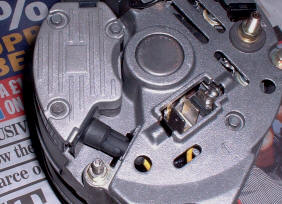
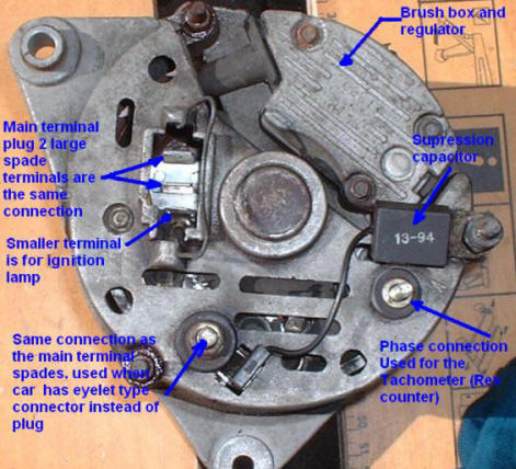
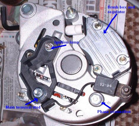
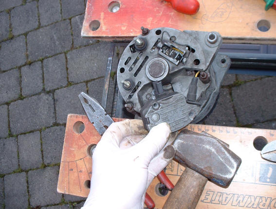
These can have plug or eyelet type terminals for the electrical connections. On the left, is the standard 65 amp fitted to the 825D (and some 820s) which is the plug type connection and a similar higher output alternator on the right which uses studs and eyelets. Either type can be encountered depending on the year of manufacture.
|
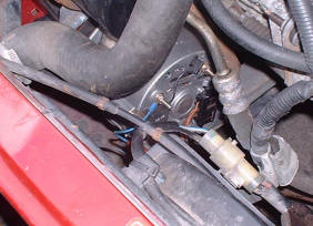
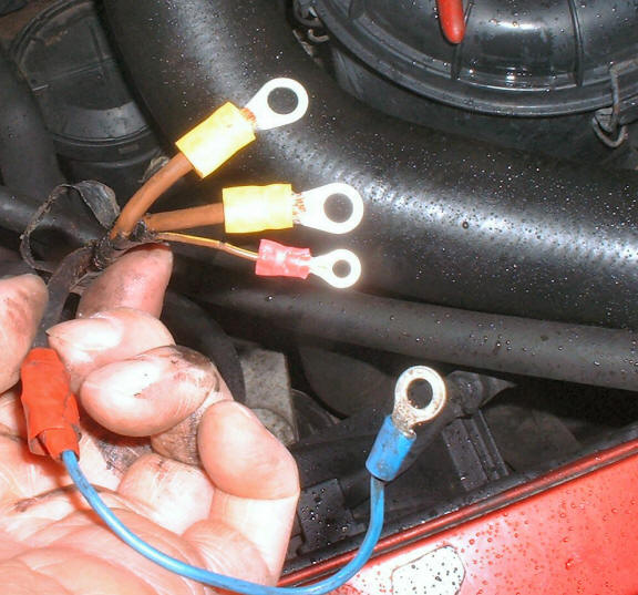
Quick note on converting connections. It is possible to use either type if the connections are adapted to suit. I had to cut off the plug and fit crimp-on cable terminal eyelets to use the alternator on the right. The 2 large cables in the plug are the same connection and both go on the main terminal stud. Small cable in the plug is for the ignition lamp, the other small cable you can see here goes to the phase (W) terminal and is for the tacho (rev counter). In this case it has a blue cable as I extended it, originally it was a white cable in black sheath. |
|
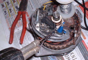
Should you want to strip down the alternator, remove all the terminal nuts and washers. Undo the three 5.5 mm hex head screws, remove the brush / regulator box. Remove two more one under the brush box, the other next to the terminal plug (the arrangement may differ a bit on some alternators). Pull the connector out of the brush box (yellow cable) Remove the suppressor and unplug its spade connector. Undo the three nuts on the machine's through bolts. |
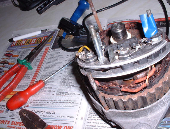
| This part is the rectifier, its job is to convert the 3 phase ac current to DC. The 2 aluminium plates hold the components. Also it has all the connectors that are used for the wiring to the vehicle's battery and electrical system |
|
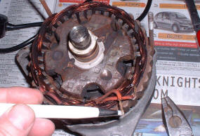
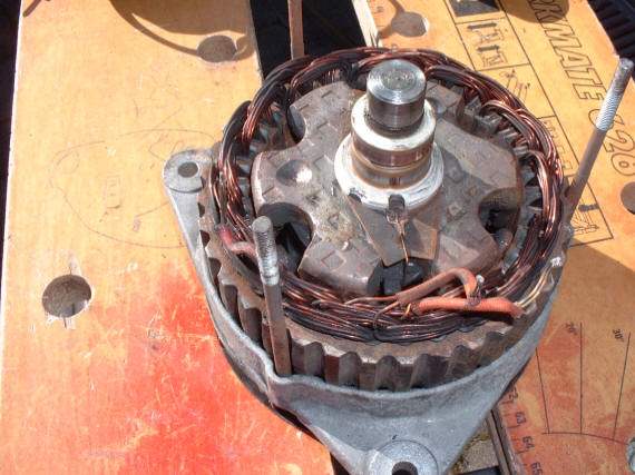
I've unsoldered the 3 sets of winding and removed the rectifier. You can now see the windings and the rotor more easily. The outer coils are the stator and as this is a 3 phase machine it has 3 sets of coils. This in the part is bolted to the vehicle and is the stationary bit. You can see in the middle the rotor, as the name suggest this is the part that rotates driven by the accessory belt from the engine. It has the winding known as the field coil, varying the amount of current that flows in this part controls the voltage output of the machine and thus its charging rate. Look at the shaft near the bearing you can see the 2 copper faced slip rings, these have the carbon brushes (remember them?) contacting by rubbing on them to carry the current from the battery through the field coils via the regulator unit. you can see one end of the field winding connecting to the bottom ring, the other end connects to the top ring (you can't see it in the photo it is behind the shaft). The ends of the windings are cleaned up ready for the replacement rectifier.
Cleaned up reassembled, fitted and back in service
The exploded diagram below is of the same type of alternator, there are some minor differences notably the pulley but it is basically the same (see photo top of page).
|