Rover 825SD 800 Coupe 825i SD1 and Land Rover Web Site
![]()
|
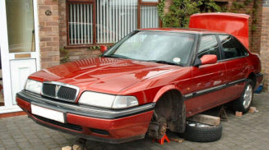
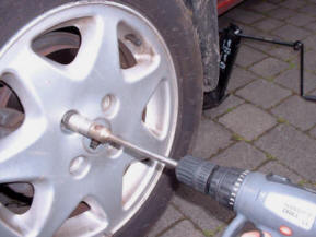
Changing the steering rack - 825 diesel Procedure is similar for other 800 models, but check workshop manual in all cases. The secret of making this job easier is to get the car jacked up as high as you safely can off the ground, a power lift would be nice but in the real world axel stands will have to do. Air tools would be nice too but my homemade cordless drill socket drive saves time and effort once the wheel nuts have been initially loosened.
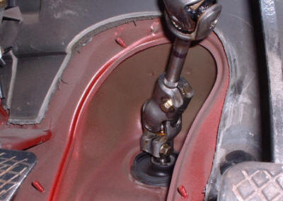
Warning! As Bruce Moxton says: "When doing anything with the steering wheel / rack, and the column universal joint has to be removed, pay attention to the number of column turns in relation to the steering rack pinion shaft, or you may fall down the same hole as I did...That rotary coupler thingy that is fitted behind the steering wheel (connects horn and airbag electric's) is internally not unlike a half wound clock spring, where the "spring" is in fact a paper thin ribbon wire, If the column is permitted to rotate freely once it has been released from the universal joint , for example in a clock-wise direction, the ribbon may become over-wound and if the universal joint is then re-fitted with the road wheels straight ahead, the first time that you turn full lock right the ribbon cable snaps, and no horn or airbag ... " I found disconnecting the universal coupling the most awkward fiddling part of the whole job, the manuals say something like "loosen the 2 bolts and slide the universal joint up the column shaft until it disengages from the rack", what it did not say was you have to completely remove the bolt, as it took me about 20 minutes to find out!.
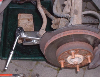
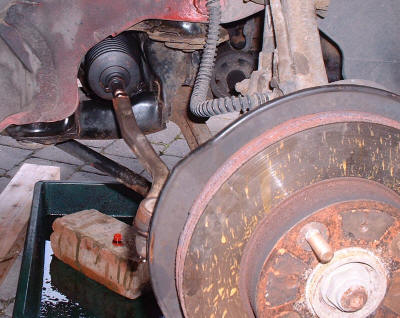
Remove the split pin and nut then split the joint on the tie rods (track rod ends) left and right. The locknuts are then loosened on the rack, and the track rod ends unscrewed these will be needed on the replacement rack. Removing these also makes the rack easier to get out. It is a good time to see if the joints are serviceable or need replacing.
There are 4 bolts holding the clamps which secure the rack to the sub frame, these are infamous for being difficult to remove as there is a captive nut inside the sub frame which can just come loose and turn without unscrewing. You can see the general arrangement form the drawing below.
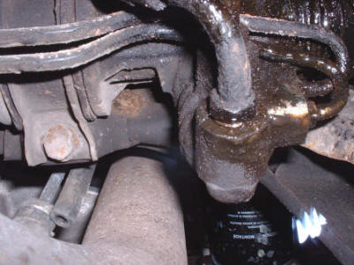
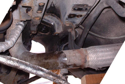
The image below shows the right clamp the bolts are slightly difficult to access because of the pipes. So it is a good idea to unscrew these first, all the fluid runs out of the system so you need a drip tray underneath to catch it. The pipes are the feed and return from the pump, they need to be kept clean so no dirt gets in the system, I wrapped the ends in several layers of cling film which also stopped them dripping fluid on me. The unions on the pipes are different sizes so you can't mix them up when fitting the rack. Notice there is a rubber O ring on each union, the manual says that these should be replaced (but since no one seemed to know where I could get news ones I re-used them, they sealed up ok when I fitted the rack). I tried to undo one of the 4 clamp bolts and it was very reluctant to move so I warmed each one up with a blow torch before continuing to undo them, they then unscrewed very easily.
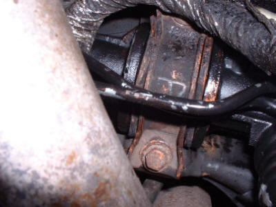
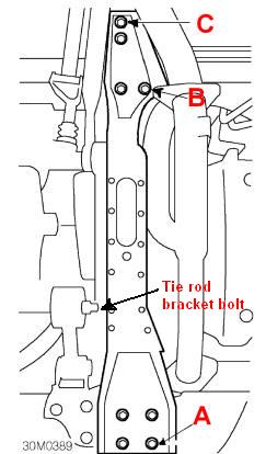
Not a pretty sight. It is also MOT time and there is no way this would pass... It is just possible to remove the rack with the exhaust down pipe in place although according to the Rover workshop manual it needs to be removed The longitudinal beam does however have to be removed.There is one 13 mm bolt that connects the tie rod bracket to the longitudinal beam. Then 4 - 13 mm bolts at the front where the towing eye is 2 at the rear end (C), and if you are wondering why it does not now come off there are 2 more (B)
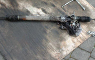
Once everything is disconnected and the rack is loose pull out the left arm as far as possible to the left this will make it easier to remove. Out with the old....
An empty space ready for the replacement.
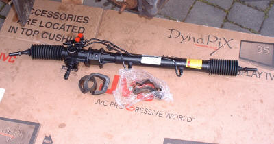
Replacement waiting to go in.
It's now time for the refitting is the reverse of stripping bit. Tighten everything to the recommended torque etc. When everything is re-installed the system needs to be purged of air or bled. This is the procedure: 1. Pull out the wiring plug
on the injection pump that goes to the fuel cut-off solenoid to prevent
the engine firing. (Petrol cars remove king lead from ignition coil for
most models, check in the appropriate workshop manual before
proceeding).
The tracking (toe in) will need to be checked when the job is finished. On the 800 the front wheels are set near enough parallel. While there are some gadgets for the amateur mechanic that can be bought to set the toe-in I prefer to get it done professionally. I found the procedure below good enough to drive the car a couple of miles to the nearest local tyre centre and let them tweak it on their equipment. For the few pounds it costs it is a good investment considering the cost of new tyres if you make a mess of it yourself! To achieve the setting roughly I followed this procedure. 1 Centre the rack
|